RoofViews

Building Science

Edge Metal Design Wall Zones 4 and 5

By James R Kirby

April 24, 2023

Edge metal

Keeping water out of a building is undoubtedly the primary function of a roof system. But one could argue that ensuring a building's roof stays in place during high-wind events is equally important. Let's face it, without a roof, it's hard to keep water out! This blog takes a look at one of the subsets of wind design of roof systems: Wall Zones 4 and 5 and their relationship with roof perimeters.

Introduction

Architects, specifiers, and roof system designers are generally focused on the wind-uplift capacity of the roof system itself. Wind resistance of perimeter edges and parapets might not be front of mind, especially given the myriad roof-system Approval Listings that can be found through DORA, FM, and UL. However, rooftop perimeters and corner areas are most vulnerable to high wind, and perimeter edge metal and copings are part of the first line of defense. Codes now include wind-design and system testing for edge metal and copings. FM also just recently (late 2021) updated RoofNav's Wind Rating Calculator to include fascia, copings, and gutters.

Edge metal and copings

The term 'edge metal' encompasses three foundational shapes that are used at a roof's perimeter: L-shaped metal, gravel stop metal, and copings for parapets. The figures below show generic shapes; ones that are often contractor-fabricated. Additionally, there are many manufacturers that provide edge metal. Some of the manufacturer-fabricated shapes are similar to those shown below. However, some are a bit more distinct and some are extruded to achieve more unique shapes.

Graphic adapted from National Roofing Contractors Association

Some examples of GAF's metal details are shown here:

Steel and aluminum are common materials used for edge metal shapes and copings. Some are galvanized; some are painted. Commonly used thicknesses range from 20 gauge to 24 gauge for steel and 0.032" to 0.040" for aluminum. The continuous cleat is typically one gauge thicker than the edge metal and coping.

Why is wind design of edge metal important?

The roofing industry has been investigating high-wind events, primarily through a group called the Roofing Industry Committee on Weather Issues (RICOWI). RICOWI was established in 1990 and has published numerous reports based on post-wind-event investigations of damage caused by hurricanes. RICOWI's most recent report, released November 19, 2019, covers their investigation of the damage caused by Hurricane Michael. RICOWI has published five reports covering their investigations of 6 hurricanes since 2004.

One of the most consistent conclusions throughout the series of 5 reports of post-event investigations is that the majority of localized roof damage and roof system failures due to high winds commonly begin at perimeters and corners. This is not surprising as the highest wind loads are at rooftop perimeters and corners. This blog about wind design and ASCE-16, among other topics, discusses the process and factors used to determine wind loads, and it provides additional information about roof zone layout.


Localized roof damage and roof system failures due to high winds commonly begin at perimeters and corners.

Not recognizing the importance of edge metal design relative to the overall wind performance of a roof system can result in edge metal installations that may not have the appropriate wind-resistance capacity. This could possibly result in localized damage and/or system failures, even when the roof system (i.e., deck, insulation, membrane) is appropriately designed for design wind loads.

The following information is intended to supplement the wind design concepts that were discussed in GAF's earlier blog about wind design and ASCE 7-16.

Roof and Wall Zones

Wind design of metal edges and copings includes an upward and an outward component, unlike the primary roof system which includes an upward component only. (The Edge Metal Testing section of this blog has more information on that topic). ASCE 7 calls the outward pressures acting on metal edges and copings Wall Zones 4 and 5. Wall Zone 4 correlates and is aligned with Roof Zone 2 (the perimeter zones), and Wall Zone 5 is aligned with Roof Zone 3 (the corner zones). The figure shows one example of a building's roof and wall zones. Case studies from this blog provide more specific information related to the figure below.

Roof and Wall Zone

What do the codes say?

The International Building Code (IBC) includes requirements for determining the wind-load capacity for metal edges and copings. This requirement has been included since the 2003 version of the IBC. In other words, edge metal and copings should have wind-resistance capacities greater than the design wind pressures. This concept is just like wind design for the primary roof system—the capacity of the system needs to be greater than the anticipated loads.

Chapter 15, Section 1504.5 from the 2015 IBC includes requirements for determining the capacity of metal edges and copings.

"1504.5 Edge securement for low-slope roofs. Low-slope built-up, modified bitumen and single-ply roof system metal edge securement, except gutters, shall be designed and installed for wind loads in accordance with Chapter 16 and tested for resistance in accordance with Test Methods RE-1, RE-2 and RE-3 of ANSI/SPRI ES-1, except Vu1t wind speed shall be determined from Figure 1609A, 1609B, or 1609C as applicable."

Chapter 16 of the IBC indirectly includes requirements for determining the wind loads acting on metal edges and copings. In Section 1609.1 Applications, the IBC states "Buildings, structures and parts thereof shall be designed to withstand the minimum wind loads…" The "parts thereof" encompasses metal edges and copings. The requirement in Chapter 15 to design and install metal edges and copings means the outward pressures for Wall Zones 4 and 5 need to be determined.

It's worth noting that the scope of the ANSI/SPRI ES-1 test method does not include gutters, which is why gutters are specifically excluded in the code language through 2018. However, SPRI, in 2016, published ANSI/SPRI GT-1, Test Standard for Gutters, which was first included in model codes in the 2021 IBC.

Edge metal testing

Determining the design wind pressures (in pounds per square foot) for Wall Zones 4 and 5 is generally the responsibility of the design professional, such as the architect or structural engineer. On the other hand, determining the capacity of metal edges and copings is generally the responsibility of the manufacturer, which may be a manufacturing company or a roofing contractor that fabricates their own metal edges, coping, and clips and cleats.

The IBC specifically lists ANSI SPRI ES-1, Test Standard for Edge Systems Used with Low Slope Roofing, as the test method to be used to determine capacity for metal edges and copings. ES-1 includes three (3) test methods (RE-1, RE-2, RE-3), each for a different edge condition.

  • The RE-1 test method is for 'dependently terminated roof membrane systems'. Essentially, a mechanically attached or ballasted membrane is considered to be dependently terminated if a "peel stop" or row of fasteners is not included within 12" from the roof edge. Without a peel stop or a row of fasteners close to the edge of the roof, the edge metal is acting as the mechanical attachment of the perimeter of the membrane. (The RE-1 figure below is rotated clockwise 115 degrees to show the as-tested configuration of the metal edge. ES-1 presumes a ballasted or mechanically attached membrane will flutter and apply load to the metal edge at 25 degrees. The rotated configuration accommodates a hanging load.)

  • The RE-2 test method is for essentially all metal edge types as long as the "horizontal component" is 4" wide or less.

  • The RE-3 test method is for copings, and RE-3 includes two tests. One test includes an upward load and a 'face' load; the second test includes an upward load and the 'back leg' load.

The wind-resistance capacity of metal edges and copings is provided in "pounds per square foot" (psf). This is appropriate because the design wind pressures are also in PSF values which makes the comparison of design wind pressures to wind-resistance capacity simple.

Where to find Approval Listings for edge metal

Similar to approval listings for roof systems, there are approval listings for metal edges and copings. Approval Listings are found on FM's RoofNav and UL's Product IQ. An account (free) is required for both. Additionally, NRCA has Approval Listings for contractor-fabricated metal edges and copings which are housed on UL's Product IQ and Intertek's Directory of Building Products.

UL

Knowing UL's Category Control Number is key to navigating UL's Product IQ. . For metal edges and coping, UL's Category Control Number is "TGJZ". After logging in, performing a search using "TGJZ" provides a list of the manufacturers that have Approval Listings with UL. Clicking on GAF's Approval Listings allows users to easy find rated Roof-edge Systems, Metal, for Use with Low-slope Roofing Systems.

Within UL's TGJZ category, GAF has 16 metal-edge products rated using the RE-2 test method and 8 coping products rated using the RE-3 test method. For example (as shown in item 3 in the screen capture above), GAF's M-Weld Gravel Stop MB Fascia B made with aluminum is rated "190 psf". That means this product can be used when the design wind pressures, which include a safety factor, for Wall Zones 4 and 5 are less than or equal to 190 psf.

FM's RoofNav

Within RoofNav, Approval Listings for metal edges and copings can be found under "Product Search" using the "Flashing" category. Most likely, users of RoofNav are familiar with the "Assembly Search" function which is regularly used to locate roof systems based on their wind-uplift ratings.

The search can be further refined within "Subcategory" by selecting Expansion Joint, Gutter, or Perimeter Flashing.

Currently, GAF has 59 Approval Listings in RoofNav: 12 for Coping, 41 for Fascia, and 6 for Gutter products. A screen capture from RoofNav shows GAF's first 20 products.

Looking closely at the Listing, the EverGuard EZ Fascia AR – Steel provides detailed information about the product itself and the installation requirements. As shown below, the listing includes multiple Ratings (i.e., wind-uplift capacity) based on material type and thickness, and face height.

While the Listing is for a steel fascia, an aluminum fascia is also shown in the detailed information. It's important to note that the chart with the "steel" listing's detailed information is the same chart that is available for EverGuard EZ Fascia AR – Aluminum, as well. Therefore, it's prudent for designers and specifiers to provide appropriate information in the specification to avoid mis-communiction about intended product use.

Take note of the material and gauge of the "retainer" (i.e., the continuous cleat). The continuous cleat is required to be 0.50 aluminum, regardless of fascia material type for this Listing. Because the strength of the cleat is a significant factor to the overall wind-uplift capacity of the metal edge (or coping), increasing the thickness of the cleat proves to be an effective method to increase performance.

FM RoofNav and Edge Securement

FM announced on its website on October 28, 2021 that "The Wind Ratings Calculator has been updated to return separate flashing ratings for roofs." The red-highlighted area shows the required capacity for Fascia, Coping, and Gutter products.

Comparison of the Minimum Wind Uplift Approval Ratings Needed (1-75, 1-90) to the Perimeter and Corner Ratings of the EverGuard EZ Fascia shows that each product type provides the required capacity, and in most cases the required capacity greatly exceeds the required rating.

Load Path

The 3 test methods included in ANSI/SPRI ES-1 standard determine the wind-resistance capacity of edge metal attached to a substrate. In other words, the measured capacity (Rating) is of the metal edge or coping attached to the wood blocking; the tests do not measure the capacity of the attachment of the wood blocking to any substrate. The National Roofing Contractors provide information on this topic. The NRCA Roofing Manual: Membrane Roof Systems—2019, on page 289 states:

"Wood Nailers and Blocking: Many of the construction details illustrated in this manual depict wood nailers and blocking at roof edges and other points of roof termination. Wood nailers must be adequately fastened to the substrate below to resist uplift loads. This especially is true at parapet walls/copings and roof edges where edge-metal shapes are fastened to wood blocking.

Among other advantages, the nailers provide protection for the edges of rigid board insulation and provide a substrate for anchoring flashing materials. Wood nailers should be a minimum of 2 x 6 nominal-dimension lumber. To provide an adequate base, nailers should be securely attached to a roof deck, wall and/or structural framing. In the design of specific details for a project, a designer should describe and clearly indicate the manner in which wood nailers and/or blocking should be incorporated into construction details. A designer should specify the means of attachment, as well as the fastening schedule for all wood nailers and blocking."

To that end, FM Global Property Loss Prevention Data Sheet 1-49, Perimeter Flashings, provides a number of recommendations for anchoring wood blocking to various types of walls and structural framing. One example of a roof/wall intersection shows the bottom nailer bolted to the bar joists to ensure an adequate load path.

In Summary

Architects, specifiers, and roof system designers are required by code (always check specific local requirements) to determine wind loads not only for the primary roofing system, but for the metal edges and copings as well. Manufacturers and fabricators are responsible for determining the wind-uplift capacity of their metal edge and coping products, as well as their primary roofing systems.

Given the relatively new requirements in the IBC for edge securement, designers, consultants, and specifiers should become familiar with both UL's and FM's approval listings for metal edges and copings. Manufacturers of metal edge and coping products are available to assist designers with selection of edge securement.

About the Author

James R. Kirby, AIA, is a GAF building and roofing science architect. Jim has a Masters of Architectural Structures and is a licensed architect. He has over 25 years of experience in the roofing industry covering low-slope roof systems, steep-slope roof systems, metal panel roof systems, spray polyurethane foam roof systems, vegetative roof coverings, and rooftop photovoltaics. He understands the effects of heat, air, and moisture movement through a roof system. Jim presents building and roofing science information to architects, consultants and building owners, and writes articles and blogs for building owners and facility managers, and the roofing industry. Kirby is a member of AIA, ASTM, ICC, MRCA, NRCA, RCI, and the USGBC.

Related Articles

Roof
Building Science

Coatings and Liquid-applied Membranes— what's in a name?

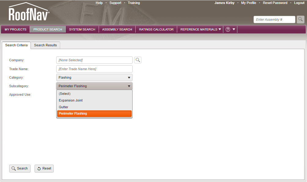
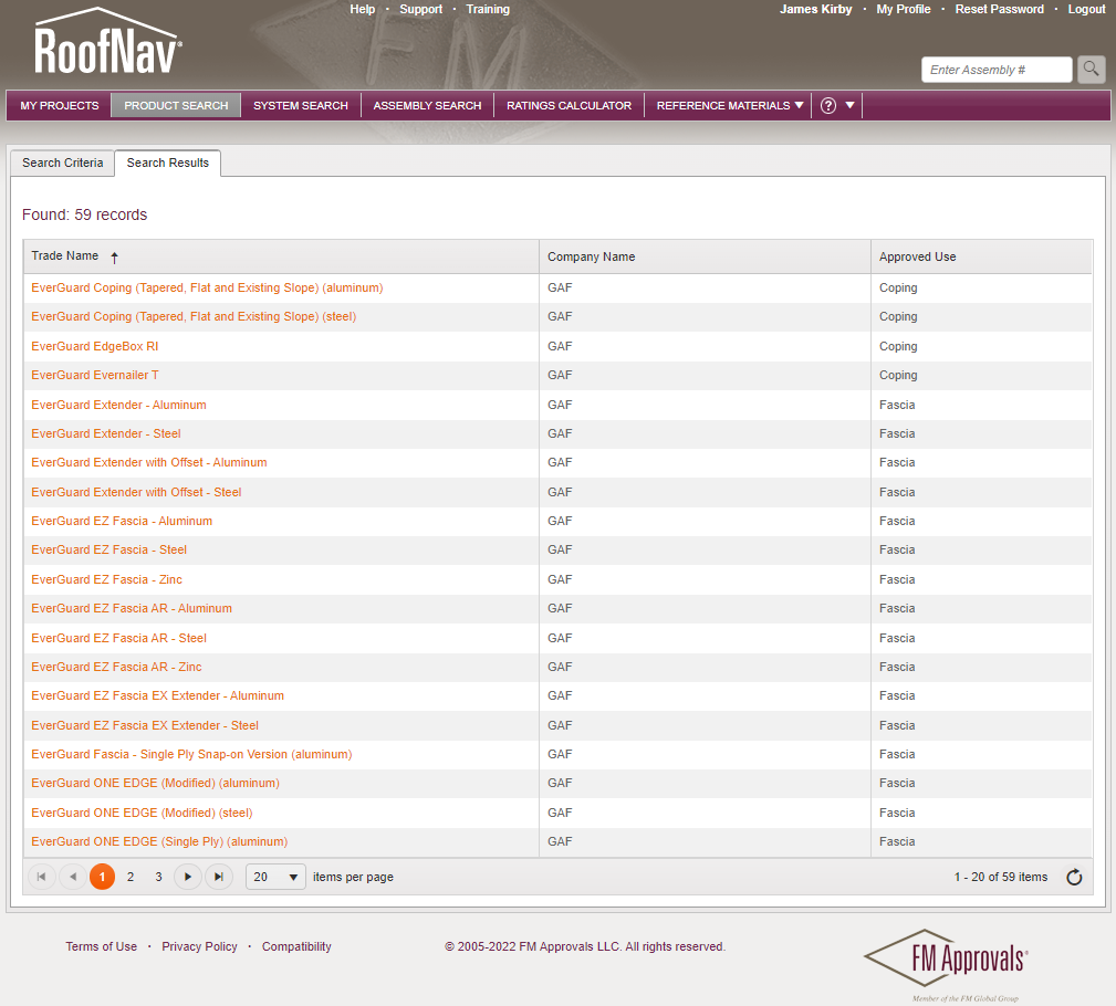
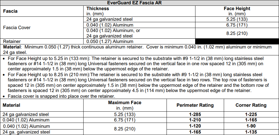
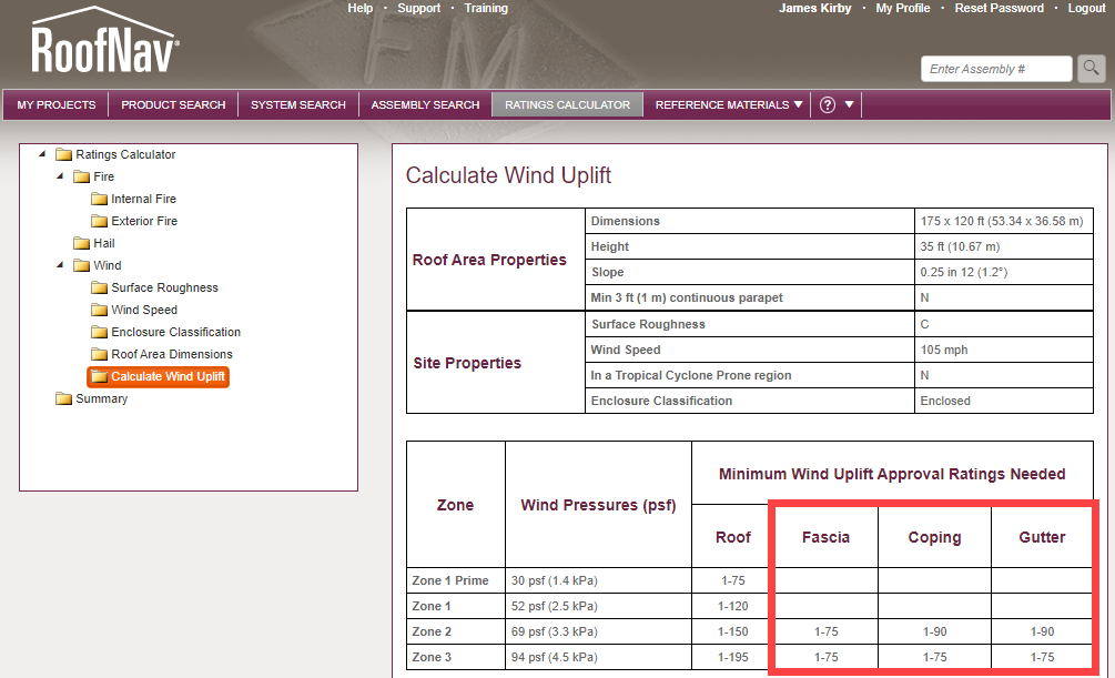
Liquid-applied roof membranes (LAM) and roof coatings (aka, maintenance coatings) are not only here to stay, their use is on the rise. This blog takes a look at how the building code and the roofing industry generally differentiate between liquid-applied roof membranes and roof coatings. There is confusion because the intended use of each is different, yet many of the materials are the same for both applications. Here's what you need to know to help understand and differentiate between the two.IntroductionCoatings have been used in the construction and roofing industries for a very long time! They have been made from many different materials--from beeswax and pitch some 5000 years ago, to lacquers and varnishes just a couple thousand years ago, to our current polymer-based materials. According to the Roof Coating Manufacturers Association, "the most dramatic advance in coating properties has come in the past 40 years, with the development of polymers1." Polymer-based coatings are used on plaza decks, parking garages, balconies, playgrounds, and roofs, for example, to provide a level of water-resistance and an aesthetically pleasing surface. Polymer-based liquid-applied membranes are used as the water-proofing layer for new roofs, replacement roofs, and roof re-cover systems. The common polymer-based materials include acrylics, silicones, and urethanes. More information about these materials can be found here.The spotlight is on these types of polymers because the materials we use for coatings are quite often also being used as liquid-applied membranes. How do we categorize and define these different installations that have different intended uses when both applications use essentially the same set of materials? This blog takes a close look at each of these product categories—coatings and liquid-applied membranes—to find their similarities and differences. And hopefully to provide clarity around the use of terms and definitions of use.Market ShareIn 2017, The Freedonia Group published a research study titled, "Liquid-Applied Roof Coatings in the US by Product and Subregion." According to that report, 11.85 million squares (1.185 billion square feet) of liquid-applied roof coating were installed in 2016. Approximately 40% was installed in the South, with the remainder essentially evenly split between the Northeast, Midwest, and West regions.The Freedonia Group reported a number of key findings that help explain the increased use of coatings."The South will be the leading US regional market for roof coatings in 2021, boosted by a high level of interest in cool roofing products and in protecting roofs against storm damage.The West will see solid growth as communities amend building codes to mandate the use of cool roofing.Liquid-applied roof coating demand in the Midwest and Northeast will be supported by rising use of roof coatings to rejuvenate older roofs instead of engaging in more costly reroofing projects."Note: The Freedonia Group's report does not separate market share based on liquid-applied materials used as roof coatings versus liquid-applied materials used as roof membranes.The use of coatings and liquid-applied membranes is increasing for a number of additional reasons as well.The use of materials that can be applied at ambient temperature is welcomed by an installer. There are no super-heated materials or open flames therefore reducing specific safety concerns.Materials are typically provided in containers sized for easy transport to and from rooftops.Common low-cost installation tools are used—brooms, brushes, squeegees; and simple, low-cost spray equipment.Using liquid-applied membranes can reduce waste created by a tear off.These materials are commonly light colored so they are reflective to help improve energy efficiency.Depending on the design (intent) and application of polymer-based materials, they can be used to extend the life of an existing roof when used as a coating, or to provide a warranted or guaranteed, waterproofing roof covering when used as a liquid-applied membrane.Defining the TermsOne way to help sort out the difference between coatings and liquid-applied membranes is to understand current definitions used in the industry. The International Building Code (IBC) is a good place to start since it is considered to be consensus-based.International Building CodeThe International Building Code does include a definition for coating, but does not include a definition for liquid-applied membrane."ROOF COATING. A fluid-applied, adhered coating used for roof maintenance or roof repair, or as a component of a roof covering system or roof assembly."IBC's definition of Roof Coating tells us three things.Coatings are fluid-applied and adhered (to a substrate)Coatings are used for maintenance or repair "Roof Repair" is defined as "Reconstruction or renewal of any part of an existing roof for the purposes of correcting damage or restoring pre-damage condition." Coatings can be a component of a roof system or roof assembly (which are the same according to ICC's definitions) "Roof Assembly" is defined as "A system designed to provide weather protection and resistance to design loads. The system consists of a roof covering and roof deck or a single component serving as both the roof covering and the roof deck. A roof assembly can include an underlayment, a thermal barrier, insulation or a vapor retarder." "Roof Covering" is defined as "The covering applied to the roof deck for weather resistance, fire classification or appearance." "Roof Covering System" is a "Roof Assembly" per IBC. Realistically, IBC's definition of Roof Coating doesn't get us that much closer to differentiating coatings and liquid-applied membranes, except that coatings are intended for maintenance and repair. And per IBC's definition, coatings can be used for Roof Repairs to "correct damage or restore pre-damage condition," but that is not how coatings are generally intended to be used.Taking a look at how Chapter 15 of IBC is arranged gives a bit of insight into IBC's perspective on coatings and liquid-applied membranes. Section 1507, Requirements for Roof Coverings, has and continues to include all low-slope and steep-slope materials used as roof coverings that are recognized by the code. This includes materials such as asphalt, wood, and slate shingles, as well as modified bitumen and single-ply roofing (and myriad others). The ICC has always included a section specifically for Liquid-applied Roofing within Section 1507, but there has never been a section for Coatings (until this year—more on that in a bit). To that end, the IBC is essentially saying Liquid-applied Membranes are categorized similarly to all other membranes that are used as roof coverings and their intended use is for "weather resistance, fire classification or appearance" (from IBC's definition as shown above). Because liquid-applied membranes are considered to be roof coverings, roof systems that use a liquid-applied membrane need to be tested for fire, wind, and impact… like any traditional membrane roof system.The liquid-applied membrane subsection within Section 1507 includes ASTM standards for materials not only used as liquid-applied membranes, but it includes the polymer-based materials (e.g., acrylics, polyurethanes, silicones) that are also intended to be used as coatings. This led to confusion within the code requirements, specifically how code officials would enforce the application of a coating product on an existing roof--as a new roof or as a maintenance item.To help with clarification and code enforcement, new language was added to the 2018 IBC in the Reroofing Section that stated a roof coating can be applied to (essentially) any existing roof without triggering reroofing requirements. The 2015 IBC and earlier versions only stated that coatings could be applied over an existing Spray Polyurethane Foam without removing any existing roofs. The IBC 2018 code language is as follows:"Section 1511.3, Roof Replacement. Exception 4: The application of a new protective roof coating over an existing protective roof coating, metal roof panel, built-up roof, spray polyurethane foam roofing system, metal roof shingles, mineral-surfaced roll roofing, modified bitumen roofing or thermoset and thermoplastic single-ply roofing shall be permitted without tear off of existing roof coverings."The additional language in the 2018 IBC was a very important step in distinguishing between coatings and liquid-applied membranes.The I-Codes were further revised regarding coatings and liquid-applied membranes in the 2021 IBC; a new section was added--Section 1509, Roof Coatings. This was an entirely new section, and importantly, Roof Coatings are not a subsection within Section 1507, Roof Coverings. This strengthens the differentiation from a code perspective that coatings are not considered to be a new roof covering. However, the IBC 2021 remains without a definition for liquid-applied roofing or liquid-applied membrane. The code ultimately relies on manufacturers' intentions for their products as the differentiating factor between coatings and liquid-applied membranes.ASTMUnfortunately, ASTM D1079, "Standard Terminology Relating to Roofing and Waterproofing" does not define either term.Industry PerspectiveWhat does GAF, a leading supplier of both systems, say about each? From GAF's page, Liquid-Applied Coating Solutions, the following descriptions are provided."What is a Liquid Membrane Roofing System?A liquid-applied roofing system consists of multiple components that come together to form a fully adhered, seamless, and self-flashing membrane. Components include liquid applied coatings and mesh membranes to create a true liquid membrane system that preserves and protects the integrity of the building." Examples of some of the leading products can be found here."What is a Roof Coating System?Roof Coatings are designed for extending the life of existing structurally sound roofs. GAF Roof Coatings are specially formulated to extend the life of roofs while protecting them from damaging effects of weather and the environment such as UV light, water and wind. GAF offers roof coatings in a variety of different technologies such as acrylic, silicone and polyurethanes to meet many different building needs and budgets."According to GAF, a liquid-applied roofing membrane protects the integrity of the building (like any traditional membrane-type roof system) and coatings are designed for extending the life of structurally sound roofs.The Roof Coating Manufacturers Association (RCMA) has a thorough description of a roof coating. RCMA is appropriately focused on the makeup of a coating (i.e., higher solids content, high quality resins) to differentiate roof coatings from what is commonly called "paint." One concept from RCMA in particular stands out—because roof coatings are "elastomeric and durable films," they provide "an additional measure of waterproofing" and can "bridge small cracks and membrane seams." The roofing industry recognizes a coating's ability to provide an amount of weather resistance / restorative properties, but this characteristic (i.e., crack bridging) is difficult to test for and quantify. And it is worth repeating, a roof coating is primarily intended to extend the service life of structurally sound roofs, not necessarily be the waterproofing layer. That is the intent of a liquid-applied membrane.FM ApprovalsLiquid-applied membranes are considered to be roof coverings by the IBC, and therefore they must be tested and have approval listings. Approval listings are used to show that systems have been tested and comply with the code requirements for roof system properties like fire-, wind-, and impact-resistance.RoofNav—New ConstructionTo that end, performing a search using the Assembly Search function within FM's RoofNav software results in a number of Approval Listings for "Liquid Applied Systems" used for New Roofs. With no manufacturer selected, the RoofNav search resulted in more than 10,000 Approval Listings for liquid-applied roofs used for new construction!Performing a second search using GAF as the manufacturer results in nearly 250 Approval Listings for "Liquid Applied Systems" used as new roofs. The nearly 250 Approval Listings include applications primarily over DensDeck™ and spray foam. When a liquid-applied membrane is used over a substrate board, such as a DensDeck™ board, a reinforcing fabric embedded between two foundation coats is used. The use of the substrate board is more common for new construction or roof replacement projects and is not common when re-covering an existing roof.An example RoofNav listing is shown here. It includes a finish coat and foundation coat with fabric over DensDeck that is adhered to polyiso, and the polyiso is adhered to a concrete deck.Wind-uplift capacity of liquid-applied membrane roof systems can be quite high. The example above has a wind uplift rating of 270 psf! Where would such a high-capacity roof system even be needed? Here's a blog that discusses design wind pressures.RoofNav—Re-coverIn addition to their use as new roofing, one of the primary attributes of liquid-applied membranes is their use over an existing roof. Searching RoofNav using GAF and "Re-Cover" as the Application results in nearly 200 Approval Listings.If a liquid-applied roof system is used in a re-cover application, the use of the reinforcing fabric seems to be tied to the specific substrate. Looking through GAF's RoofNav Approval Listings for Re-cover Liquid-Applied Systems, reinforcing fabric is used when re-covering traditional multi-ply asphaltic membrane roof systems, or TPO and PVC membranes. However, when the substrate is a standing-seam type metal roof panel, a metal-faced composite panel, or spray foam, the fabric is not listed as a necessary component of an Approval Listing.It's important to recognize that an FM Approval Listing also provides information about the internal fire rating, exterior fire rating, and hail ratings. Many liquid-applied roof systems achieve Class A Exterior Fire ratings as well as Moderate or Severe Hail ratings. For a short tutorial on using RoofNav's Assembly Search feature, watch this video.In SummaryThe following chart is intended to provide examples of similarities and differences between coatings and liquid-applied membranes.ConclusionSimply put, coatings are used to provide protection from the elements and help extend service life. Coatings are not installed as 'membranes' so they are not intended to seal leaks or be considered "waterproof". Liquid-applied membranes are considered to be just that—membranes—and are used as the covering in new and re-cover roof systems. Liquid-applied membranes are tested as systems and have approval listings just like traditional asphaltic, modified bitumen, and single-ply roof systems.References:1RCMA.org/history-of-roof-coatings

By Authors James R Kirby

April 07, 2023

Commercial Roof
Building Science

IBC and FM—What's the Difference When it Comes to Wind Design?

Introduction Wind design of roof systems can be confusing from an engineering perspective. Wind design can also be confusing because the International Building Code (IBC) provides specific requirements, but so does Factory Mutual (FM). If FM is specified, do the IBC requirements need to be followed? What is the wind-design strategy for FM-insured and non-FM-insured buildings? This blog will discuss the following: IBC is a model code; FM is an insurance company Compliance with the local building code is a legal requirement; FM is elective (a building owner has the ability to select their insurance carrier) IBC references the ASCE 7 standard; FM provides wind-design methodology via the Ratings Calculator and Assembly Search functions within RoofNav FM-insured buildings must comply with both the IBC and FM requirements Specifying "FM" could trigger the "FM process" unknowingly for non-FM insured buildings What is the issue? In roofing specifications, architects have been referencing Factory Mutual (FM) for many decades, especially when it comes to wind design of commercial roofing systems. "Meet FM requirements," "Provide a 1-90 roof system," or just simply "Meet FM" are phrases inserted into specifications. Do these phrases supplant the need to follow the wind-design requirement of the International Building Code (IBC)? (Spoiler alert: The answer is a resounding "NO".) The Basics The IBC is a model code, developed by the International Code Council. A model code, such as the IBC, is intended to be adopted by municipalities (e.g., state, city) as the locally enforced building code. The model code can be adopted as-is, or with language removed, with language added, or both. The local building code is enforced through local building code officials. And, very importantly, meeting the local building code is a legal requirement and there can be ramifications when the local building code is not met. Commercial buildings are required to meet the IBC as adopted and amended by the local jurisdiction. For wind design, the IBC requires a roof system be designed based on ASCE 7, Minimum Design Loads for Buildings and Other Structures. (More on the specifics later.) FM Global is an insurance company and a purveyor of design and installation documents for roof systems (e.g., Loss Prevention Data Sheets 1-28, Wind Design). FM Approvals is a testing facility, a third-party certification body, and a developer of Approval Standards (e.g., FM 4470, Single-Ply, Polymer-Modified Bitumen Sheet, Built-Up Roof (BUR) and Liquid Applied Roof Assemblies for use in Class 1 and Noncombustible Roof Deck Construction). FM Approvals also maintains RoofNav (www.RoofNav.com), which provides access to FM Approved roofing systems and related installation recommendations from FM Global. RoofNav is likely the FM tool that is frequently used by architects and roof system designers who are searching for and selecting approved roof systems. This is why many architects and specifiers include some reference to FM in roof system specifications. IBC Wind Design Method Model building codes, such as the 2018 IBC, when adopted by a local jurisdiction, become the legal requirements for construction. The IBC specifically states, "The I-Codes, including this International Building Code, are used in a variety of ways in both the public and private sectors. Most industry professionals are familiar with the I-Codes as the basis of laws and regulations in communities across the U.S. and in other countries." A more succinct way of stating this is—the local building code is the law. Within the IBC, the building code requirements for roofing and rooftop construction are found in Chapter 15, Roof Assemblies and Rooftop Structures. Section 1501.1, Scope, states "The provisions of this chapter shall govern the design, materials, construction and quality of roof assemblies, and rooftop structures." Wind resistance of roof systems is included in Section 1504, Performance Requirements, and Section 1504.1, Wind resistance of roofs, requires roofs be designed for wind loads according to Chapter 16, Structural Design. Section 1609, Wind Loads, incorporates by reference the standards set forth in ASCE 7; this section includes the following language. "1609.1.1 Determination of wind loads. Wind loads on every building or structure shall be determined in accordance with Chapters 26 to 30 of ASCE 7." It's worth noting that the version (i.e., year of publication) of ASCE 7 is not specified in the body of the code; versions of referenced standards are found in Chapter 35. The key point is that the IBC directs users to ASCE 7 to determine design wind pressures (DWP) for roof systems. (More on determining DWP can be found in this blog.) To continue a bit deeper into the 2018 IBC, Section 1504.3 is the directive to designers to design roofs to resist design wind pressures. "1504.3 Wind resistance of non ballasted roofs. Roof coverings installed on roofs in accordance with Section 1507 that are mechanically attached or adhered to the roof deck shall be designed to resist the design wind load pressures for components and cladding in accordance with section 1609.5.2." It's important to recognize that Section 1504.3 specifically ties the wind design of nonballasted roofs to ASCE 7 by referencing a subsection of Section 1609. Additionally, Section 1504.3.1 is the directive to manufacturers to test roof systems to determine wind uplift capacity. "1504.3.1 Other roof systems. Built-up, modified bitumen, fully adhered or mechanically attached single-ply roof systems, metal panel roof systems applied to a solid or closely fitted deck and other types of membrane roof coverings shall be tested in accordance with FM 4474, UL 580 or UL 1897." This section provides 3 code-approved test methods to choose from to perform wind-uplift-capacity testing. FM 4474, American National Standard for Evaluation of Simulated Wind Uplift Resistance of Roof Assemblies Using Static Positive and/or Negative Differential Pressures UL 580, Standard for Tests for Uplift Resistance of Roof Assemblies UL 1897, Standard for Uplift Tests for Roof Covering Systems These tested systems are found in Approval Listings from organizations like FM, UL, and SPRI. These two videos provide more information about FM Approval's RoofNav and SPRI's Directory of Roofing Assemblies. What's NOT Stated in the IBC Nothing in the model code sections referenced here or any other related model code sections within IBC contains a provision that allows a wind-design method other than ASCE 7 to be used. In other words, using FM's RoofNav for wind design of roof systems is not a replacement for following building code requirements that mandate the use of ASCE 7. Of course, designers should always check with the specific requirements of the local building code to determine if the use of FM's RoofNav is allowed for code compliance. FM We've established that FM Global is an insurance company that provides installation recommendations and FM Approvals provides design information, as well as FM-approved listings. In order to receive an FM Approval Listing, a roof system must be tested in accordance with FM 4470, Single-Ply, Polymer-Modified Bitumen Sheet, Built-Up Roof (BUR) and Liquid Applied Roof Assemblies for use in Class 1 and Noncombustible Roof Deck Construction. FM 4470 includes a battery of tests intended to help determine the long-term performance of a roof system (clearly an important issue for an insurance carrier!). FM 4470 includes the following mandatory tests to be performed: Combustibility (from above and below the roof deck) Wind uplift (FM 4474 is the test method used to determine wind uplift capacity) Hail resistance Water leakage Foot traffic Corrosion Susceptibility to heat damage FM 4470 also includes requirements for a manufacturer's in-house quality control program that includes an audit program, field inspections during installation, and additional manufacturer responsibilities if products' construction or components are revised. The use of FM 4470 results in a roof system with a "1-60" or "1-75" listing, for example. The "1" represents the roof system is Class 1 for fire resistance (combustibility) from below the deck. The second (e.g., 60, 75) represents the wind-uplift capacity (in pounds per square foot) of the roof system. It is important to recognize that FM 4470 is not listed as one of the test methods for wind-uplift capacity in the 2018 IBC, which means the IBC does not require a roof system to be FM-approved! FM 4474, American National Standard for Evaluation of Simulated Wind Uplift Resistance of Roof Assemblies Using Static Positive and/or Negative Differential Pressures, is a test method to determine wind uplift capacity of roof systems. As noted previously, FM 4474 is the wind-uplift test method that is required to be used within FM 4470 for an FM Approval Listing. FM-insured buildings Buildings that are FM insured are commonly required by FM to use a roof system that has an FM Approval Listing. More specifically, roof systems intended to be used on FM-insured buildings should use RoofNav to determine wind loads (via the RoofNav Ratings Calculator) and find Approved roof systems (via the RoofNav Assembly Search). Non FM-insured Buildings To broadly say "Meet FM" or "Meet FM requirements" in a spec could be interpreted to mean—for non-FM insured buildings—that the wind-design process, deck securement, and roof system installation should follow ALL of the specific FM processes and recommendations that are used for FM-insured buildings. As the architect or specifier working on a building that is not insured by FM, is the vague specification language truly intended to bring the entire "FM process" into the wind design and installation of a roof system? Probably not. It is more likely the vague specification language referencing FM is intended to be a way to state that the assembly must meet local building code requirements for wind design. Saying "Meet FM" or "Meet FM requirements" does not preempt or override the requirements of the IBC, as adopted by local building code, that are legally required to be performed by the Architect of Record when it comes to wind design of roof systems. (Additional information about code requirements for wind design can be found here.) Conclusion The IBC, as adopted by local building codes, is required by law and references ASCE 7 as the standard to be used for determining design wind pressures for roof systems. The IBC does not include FM's wind-design process (e.g., RoofNav's Ratings Calculator and Assembly Search functions) for determining DWPs. Vague specification language referencing FM may unnecessarily bring the FM wind-design process into play. The IBC also provides 3 test methods for determining wind-uplift capacity of roof systems—UL 580, UL 1897, and FM 4474. It is important to recognize that FM 4474 is a test method used by manufacturers to determine wind-uplift capacity, and FM 4470 is a comprehensive standard covering many aspects of roof system performance. Specifying and only using FM's wind design process in lieu of following the wind-design requirements in IBC, as adopted by local building code, means the minimum legal requirements for wind design technically may not have been met. Understanding the roles that IBC and FM play in the roofing industry is key to understanding the role of the architect or specifier, and the manufacturer when it comes to wind design of roof systems. This blog is for informational purposes only and is not intended to be construed or used as professional design advice. Consult a design professional to ensure the suitability or code compliance of a particular roofing system for any particular structure.

By Authors James R Kirby

July 16, 2021

Woman sitting in open window under steep-slope shingle roof
Building Science

Ventilation of Steep-Slope Roof Systems and Transitions

Ventilation for steep-slope roof assemblies is often misunderstood. One must not only understand the code requirements, but be able to translate them into real-world installations. Building codes have requirements for ventilation of steep-slope attics and enclosed rafter spaces. Balanced ventilation — nearly equal amounts of intake and exhaust — typcially provides efficient ventilation. Transitions between low-slope and steep-slope roof areas require more distinct intake and exhaust details than traditional eaves/soffits and ridges. This blog provides information relating to ventilation for educational purposes only. Designing ventilation to meet the specific needs of a given project remains the responsibility of the architect, specifier, design professional or roofing contractor. Damage due to inadequate ventilation is typically excluded from coverage under manufacturer warranties. Introduction Residential attic ventilation was a requirement in the very first edition of the Building Officials Conference of America's (BOCA's) model building code that was published in 1948! Even though this requirement has been around for decades, it is still often misunderstood. Perhaps it's the words used and perhaps it's because the code isn't quite specific enough. When discussing residential construction, we often hear something like "We need to vent the roof," when we really mean that we need to vent the attic. We don't ventilate steep-slope roofs themselves; we ventilate the space beneath the roof. More specifically, ventilation is needed for the space under the roof system that is above the insulation in the attic floor. That's the space we know most commonly as an attic (when the insulation is located in/on the floor of the attic). Benefits of attic ventilation Ventilation of an attic space provides a couple of benefits: it lowers the attic temperature and also helps reduce excess moisture that can accumulate. These benefits occur when the air in an attic space is replaced by outside air that is a lower temperature and has less moisture in it (i.e., lower relative humidity). While this seems obvious for most parts of the US, even in warm, humid locations like Miami and Houston, the majority of the time the ambient air is cooler and contains less moisture than the air in an unconditioned attic. Code requirements The International Residential Code (IRC) applies to one- and two-family dwellings, and because of that, most in the roofing industry relate attic and rafter ventilation with residential steep-slope construction, which is a valid and correct presumption. However, the International Building Code (IBC), which covers all buildings other than one- and two-family dwellings (e.g., commercial, industrial, institutional, large residential), also includes information about attic and rafter ventilation because a large number of these types of buildings also include steep-slope roof systems. To that end, both the IBC and the IRC have requirements that apply to the ventilation of attics and enclosed rafter spaces. These requirements are included in Chapter 8, Section R806, Ventilation in the 2018 IRC, and in Chapter 12, Section 1202, Ventilation in the 2018 IBC. (Free versions of the codes are found here.) Both the IRC and IBC include nearly identical requirements, albeit the code sections are arranged slightly differently. The following summarizes the requirements: The requirements for ventilation are specific to enclosed attics (insulation on the floor of the attic) and enclosed rafter spaces (where ceilings are applied directly to the underside of roof rafters/framing members and insulation is between rafters above the ceiling). Vents should not allow the entry of rain and snow. Vents are to be protected from the entry of small 'creatures' such as birds and rodents. Corrosion-resistant materials are to be used, and minimum and maximum sizes of vent openings are provided. The minimum net free vent area is 1/150 of the vented space. The minimum net free vent area can be reduced to 1/300 when both of the following conditions are met: In climate zones 6, 7, and 8, a Class I or II vapor retarder1 is installed on the warm-in-winter side of the ceiling (i.e., attic floor). A "balanced ventilation"2 method is used. 1Vapor retarders — An example of a Class I vapor retarder is a polyethylene sheet, and an example of a Class II vapor retarder is kraft-faced fiberglass batt insulation. The polyethylene sheet or the kraft-paper side of the insulation should be installed immediately below the attic floor insulation layer in order to meet the requirements shown above, regardless if it's a traditional attic or an enclosed rafter space. Importantly, but not specifically required in the codes, these vapor retarders should be installed and detailed to also act as air barriers to prevent warm, moist air from the interior spaces from leaking up into the attic. 2Balanced ventilation — "Balanced ventilation" means 40% to 50% of the required ventilation area is located in the upper portion of the attic, and the remainder is used for intake at the eave or within the bottom 1/3 of the attic area. Commonly, exhaust vents consist of continuous ridge vents or static vents no more than 3 feet from the ridge (measured vertically). Intake vents within soffits or eaves are common, and in-plane intake vents (such as GAF Cobra IntakePro®) are used when eaves and soffits are not built to include intake vents. Current construction methods commonly incorporate the balanced ventilation method for residential attic construction and, therefore, the 1/300 ratio is used to calculate ventilation amounts. The 1/300 ratio means 1 square foot of attic ventilation (evenly split between intake and exhaust) is needed for every 300 square feet of attic floor space. The intent of the requirements for balanced ventilation is that there is more intake than exhaust. This is quite important! Having more intake than exhaust means there will be proper convective flow from eave to ridge. Because warm, moist air is more buoyant than dry air, the warm, moist air rises and is exhausted at the upper portion of the attic. When there is less intake than exhaust, the lack of intake can "choke" the system, reducing the overall effectiveness of the attic ventilation system. Balanced ventilation and reroofing Balanced ventilation is not only important for new construction, but it is an important objective for steep-slope reroofing projects, especially for residential construction. During reroofing, if the amount of exhaust is increased (e.g., by adding a ridge vent with more total exhaust capacity than the previous static exhaust vents), the amount of intake ventilation should be determined and increased as necessary to create a balanced system. If the amount of intake is too little, intake air will come from other sources! A lack of intake at the eave/soffit can lead to air being drawn into the attic from the interior of a residence through can-lights, ceiling vents, and attic-access locations. Believe it or not, air can be pulled from basements and crawl spaces through the cavities in interior walls up into the attic spaces. These "interior" sources of air can contain warm, moist air that can be detrimental to attics, causing condensation and other moisture problems that didn't previously exist. The interior air may not have been drawn into the attic if the system was previously balanced, even if undersized. So, be cautious when increasing the exhaust amounts on existing buildings without assessing the intake amounts. Addressing any 'intake' deficiencies during steep-slope reroofing projects can help ensure that ventilation is balanced and functioning as intended. This post isn't going to dive into calculating the required amounts of ventilation. To better familiarize yourself with that calculation, use the GAF Attic Ventilation Calculator. The calculator determines the minimum amount of exhaust and intake, and the minimum lineal feet of specific GAF products, such as Cobra Rigid Vent 3 for warmer climates, Cobra SnowCountry for cold and snow climates, and Master Flow Undereave Vents, is provided to meet those calculated amounts per the 1/300 ratio. Modern changes to construction: Cathedral ceilings Historically, given that attic ventilation requirements go back decades, the code originally applied only to the traditional attic space under a steep-slope roof — that is, attics with insulation located at the floor of the attic/in the ceiling of the upper floor of a residence. Today, and in the recent past, the traditional attic space is often now a usable, conditioned space. That means the ceiling is attached to the underside of the sloped rafters creating a cathedral ceiling, or some form of that. The traditional attic is turned into occupied space, and the result is an enclosed rafter space. (Remember the code language from earlier that says "attics and enclosed rafter spaces"?) Chapter 8, Section R806, Ventilation in the 2018 IRC, and Chapter 12, Section 1202, Ventilation in the 2018 IBC provide an option for ventilation when a cathedral ceiling is installed with insulation under the roof deck in the enclosed rafter space. The specific requirement for this type of construction states that there must be a minimum 1" vent space in each rafter space directly beneath the roof deck above the insulation. This can be somewhat difficult to construct and maintain continuous air flow. Also, once constructed, inspection and repair is difficult without removal of interior drywall and/or exterior soffits and eave components. The graphic, from the International Association of Certified Home Inspectors, is an example of ventilation of the construction method that incorporates enclosed rafter spaces. The 1" minimum required air space (under the deck between the rafters) is considered to be the vented space, and that means the requirements for the protection of openings from snow, rain, and small creatures, as well as corrosion resistance and sizes of vent openings, are applicable. The minimum net free vent area requirements may also apply when there is a vent cavity/air space under the deck and above the insulation between the rafters. In other words, the vent space size is calculated the same way as the traditional attic space. Specifically, the 1/150 ratio still applies, and in order to reduce the amount of ventilation to 1/300, the additional requirements for Class I and II vapor retarders in Climate Zones 6, 7, and 8, and balanced ventilation also apply. At no time can the vent space between the rafters above the insulation and below the roof deck have less net free vent area than is required for intake and exhaust vents. The depth of the air space may need to be greater than 1" deep to accommodate enough air flow to provide proper ventilation. For example, if the 1/300 ratio determines that 10 square inches per lineal foot of net free vent area (NFVA) is required, a 1" deep air space is appropriate. However, if 20 square inches per lineal foot of NFVA is required, then a 2" deep air space is needed to provide appropriate air flow. Calculating the required depth of the air space to match the amount of NFVA for eave intake and ridge exhaust should take into account the ratio of rafter-to-open air space for continuous eave and ridge vents. Tricky transitions There are many options to vent eaves and ridges on traditional residential construction. However, where a steep-slope roof transitions to a low-slope roof (and vice-versa), the methods to provide intake and exhaust ventilation can be a bit trickier. Where a low-slope roof abuts the low edge of a steep-slope roof, a good option for intake vents is to use a "deck-level" intake vent, such as GAF Cobra Intake Pro. This type of intake vent is intended for use where there are no eaves or soffits available to install traditional intake vents. Due to the potential for water to build-up at the transition from the low-slope roof to the steep-slope roof due to rain, sleet, or snow, or some combination thereof, it's logical to install a "deck-level" intake vent up-slope at least 2 courses. It is best to locate an intake vent far enough up-slope to help prevent snow from blocking the vents, as well. The National Roofing Contractors Association (NRCA), in The NRCA Roofing Manual: Steep-slope Roof Systems—2017, provides the following detail for a "Steep- To Low-Slope Roof System Transition." A key element is that NRCA shows the bottom edge of the shingle roof is a minimum of 10" from the low slope transition point. This helps prevent water intrusion through the steep-slope roof. And if the "deck level" intake vent is up 2 courses, the intake is some 20" from the surface of the low-slope roof (albeit measured along the slope, not vertically). Where a low-slope roof abuts the upper portion of a steep-slope roof, detailing and constructing the exhaust vent is needed in order to properly terminate the low-slope roof. The concept, in general, is to use one-half of a ridge vent, and that likely means this detail is built in place (it does not appear that there are pre-manufactured vent devices for this type of installation). A gap is needed at the top of the sloped deck to allow air to move from the attic or enclosed rafter space up and out the vent material. As shown in the detail below, wood blocking and vent materials are installed on top of and along the upper edge of the steep-slope roof covering. A nailable top layer (e.g., a 2x6) is installed to keep the vent material in place and to act as a nail base for the termination of the low-slope roof. In addition to the ventilation details needed at these types of transitions, it's important to remember the transition details need to consider the continuation of the water, air, thermal, and vapor boundary conditions. You can refresh your knowledge with this GAF blog post. What the codes mean but don't say Simply put, ventilation of attics and enclosed rafter spaces occurs outside of the thermal layer. The code requirements have been developed and instituted based on this, but codes don't explicitly state it. That leads to confusion by some who ask if low-slope roofs need to include ventilation. Let's think about that. For membrane roofs with insulation above the deck (that is, compact roofs), where exactly would the ventilation space be located? Between the insulation and the membrane? That's not how low-slope roofs are constructed. The next possible location for a ventilation space would be under the deck, which means the ventilation is on the conditioned side of the thermal layer for a low-slope, compact roof system, and that is illogical. Expensive conditioned air would easily escape from the building, and unwanted exterior air would easily enter. That would be like leaving doors and windows wide open while air-conditioning or heating a space. One very important point — even if there was a way to provide intake and exhaust vents as part of a low-slope roof system, a horizontal air space provides no path for warm moist air to rise to an exhaust vent. Another way to say it — natural convective flow does not really happen in a horizontal space. In conclusion We ventilate our attics and enclosed rafter spaces to remove unwanted heat and moisture. According to the GAF Pro Field Guide for Steep-slope Roofs, attics can reach up to 165° F, and for asphalt shingles, excessive heat can reduce shingle life. The Guide provides information why venting makes sense, and there are a couple other details available for review and use. Keep your ventilation balanced!

By Authors James R Kirby

June 07, 2021

Don't miss another GAF RoofViews post!

Subscribe now